


Liquid Level Control with PLC
This is a very simple Control design where we make use of PLC to control the level of liquid in a tank while displaying the liquid level in the field as well as in the control room. we are going to carry out the design from instrumentation to the control while demonstrating how we can apply ACECATECH APPs to reduce our engineering time. only details that are relevant to the design process are discussed here.
CONTROL PHILOSOPHY
In this simple level control application we want to control the level of liquid in a tank which is 10m high by activating a motor pump when the fluid level in the tank is 9.5m. the motor will pump out the liquid from the tank until the level is 0.5m. we are also going to have a display of the process variable in the control as well as in the control room as shown below.
CURRENT LOOP DESIGN
Here we make use of ACECATECH APP. 1.0 to generate the required parameters for our loop design. we look up the manufacturer’s specification sheet for the transmitter (voltage range of operation and current signal range), field display/indicator (get the input impedance), PLC (get the input impedance, and current signal range of operation) and the loop voltage supply.
Let assume we obtain the following from the spec. sheets of the our instrument and controller.
Transmitter working voltage range: 12-30v, current signal range :4-20ma
Display/indicator input impedance: 500 ohms
PLC input impedance: 250, current range: 4-20ma
let assume that the distance between our transmitter and controller is 800m.
we proceed by plugging these values in our current loop design app ACECATECH APP. 1.0 by selecting desired wire size starting from the minimum we find that wire size o.75mm2 and above looks good for the design both at max. current and minimum current level. but voltage drop of 10.17v at maximum current is way too close to the transmitter lower range of operation so we choose 1mm2 for our application.
PLC PROGRAMMING
Many PLC have special function block or already made routine to scale analog signal to correspond to the actual process values in the field. however, some lower end PLCs and older ones may not have this capabilities so you have to write the software routines yourself. In fact, some times it is even desirable to write this routines yourself as you may want to control how the PLC handles the hardware flags. Here we make use of our online app ACACATEC APP 1.7 software scaling equation to generator two equations. the first equation is suitable for real/float point number arithmetic. The second equation suitable for integer arithmetic suitable for PLC that do not have float point math capabilities. for this example we are going to demonstrate how to use this app for PLC without float point capabilities as their analog scaling are pretty more involved.
for this PLC programming lets choose Allen Bradley PLC SLC 5/01 which doesn’t have special function for scaling and do not have float math capabilities either
We start by entering our scaling parameters in ACACATEC APP 1.7
Raw input value: 3277-16384
process output value: 0-10m
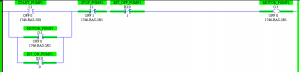
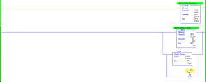
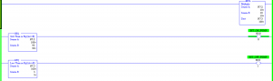
from our equation software for integer math we generate the following equation:
Xo=10/13107(Xi-3277)
in the software program we make use of mathematical functions: subtraction, multiplication and double division while storing the data of the equation as integer type.
NB in our program you must multiply before you divide! (sorry for violating the principle of BODMAS as integer math arithmetic seems to flout this rule as it is obvious from the equation.). Also, note that the product of 10 and (Xi-6400) in our equation will at higher value of Xi produce a value in excess of 32767 (ie 16 bits) which is the highest value an integer data type can store. This will prompt an over flow flag notifying that an error has occurred. for AB plc the over flow trap bit s: 5 is set. However, we apply some tricks to beat this in our program by unlatching the bit and using the double divide function to divide the result of operation in the math register which can store 32 bits with the divisor and store the result of operation in an integer register.
the program is as shown below.
For further inquiry you can do us a mail at: info@acecatech.com
or Cal: +2348160052942.
check out some of our other online APPs.
Current loop design (ACECATECH APP. 1.0)
Voltage to voltage hardware scaling (ACECATECH APP. 1.1)
Voltage to current hardware scaling (ACECATECH APP. 1.2)
Current to voltage hardware scaling (ACECATECH APP. 1.3)
current to current hardware scaling (ACECATECH APP. 1.4)
Hardware-software scaling (ACECATECH APP. 1.5)
software scaling Equation Generator (ACECATECH APP. 1.6)
Instrument five-point Calibration generator (ACECATEC APP. 1.7)
Note: The use of these simple Apps is to simplify and hasten up your design and engineering time as the Apps are developed with best engineering practices. you are however advised to strongly adhere to your manufacturer specifications and carry out independent and discretionary tests before implementing your design as we will not be held liable for any damage or loss caused by implementing any of our APP. design.