


Current loop design (ACECATECH APP. 1.0)
This online App serves as a guide to instrument/automation engineers and technicians in other to design and analyze their current loops. It shows the limiting wire size as well as the transmitter limiting voltage range for a given supply voltage and total loop resistance. The analog-current signalling in instrumentation and control is one of the most predominant means of communication between the field instrument and the controllers. current loops if not properly design can be very problematic.
It must be noted that if a transmitter is not seeing enough voltage at the maximum loop current it will result to the transmitter mal_functioning and giving inaccurate results. If the transmitter voltage is two high perhaps higher than its maximum rating probably at the minimum loop current the transmitter might get damaged. so this online app provide you the necessary guide in your design and cable selection for your loop and all you need to do is to enter your design parameters.
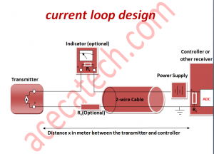
TRANSMITTER
The transmitter transmits current signal from the field via the loop cables to the controller. for your design parameter you can fetch the minimum and maximum working voltage range from your transmitter’s data sheet. (eg 10-30v)
INDICATOR (optional)
Indicator or Display are usually found in process loops often to give a visual display of the process variable in the field. the parameter you need for indicator or display is the input impedance from the data sheet or from measurement/calculation.( eg 250Ohms)
POWER SUPPLY
The power supply provides the necessary electric power that powers the loop. The two wire transmitter system are usually loop powered and must provide enough voltage to maintain the current in the loop. the parameter we need here for our design is the voltage level of our supply (eg 24V)
RECEIVER/CONTROLLER
This can be any microprocessor based receiver that has the capability of ADC processing. example PLC, DCS, I/P converters, etc. The parameter we need here is the input impedance. (eg 250Ohms)
SERIES RESISTOR (optional)
This include any type of discrete resistor found along the loop. It may come in form of voltage limiting resistor, test resistor, scaling resistor, etc. for your design parameter you find the sum of all series resistance along the loop. (eg 150Ohms)
THE CABLE
the cable is the electrical link between the transmitter and the receiver and connects all the loop elements. different sizes/gauges of wire comes with different voltage drop per length with the smaller ones with higher drops. the parameter to be entered here is your desired wire size/gauge perhaps starting from the smaller sizes/gauges, the software will suggest if the size is adequate for your application.
DISTANCE
the distance is aptly the displacement from the transmitter to the receiver along the cable. the needed parameter here is just the distance from the transmitter to the receiving instrument taking due cognizance of the path through which the cable traces. ( eg 500m)
LOOP CURRENT
This is the range of current signal that flows in the loop. here the parameter of interest is the upper and lower range of the current signal (eg 4-20ma)